
Flange-Mounted Force Transducers
Opposing bolted flange faces carry the axial load without a large external threaded adapter. This is a compact shear-web architecture; it measures axial force rather than a complete six-axis force/torque vector.
Confirm the bolt circle and center thread.
500 N–200 kN family request envelope · Alloy steel or stainless steel; flange interfaces by drawing. Compact test fixtures · robot flange axial loads · automation tooling.
| Model family | Capacity request · kN / lbf | Outer Diameter (OD) · mm / in | Height (H) · cell / with base | Center Thread · Metric / UNF | Outer Bolt Circle · BCD & Hole Count | Net Weight · kg / lbs |
|---|---|---|---|---|---|---|
| MT-PLC-FLG | 0.5–200 kN 112–44,962 lbf | Project drawing required | Cell / base / button stack reviewed separately | Two flange patterns / pilot review | BCD, count, bore, counterbore and pilot on released drawing | Sensor and full assembly mass confirmed before freight |
For an installed replacement, supply the original drawing or measured envelope. Original manufacturer reference dimensions are labeled separately; they are not approved MT-PLC dimensions.
Download the original / proposed interface worksheet (CSV) ↓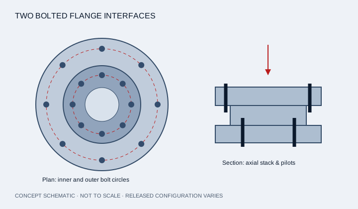
Original engineering illustration. Geometry and fasteners depend on the agreed configuration.
Define the load envelope behind the number.
- Supply both face drawings, pilot diameters and bolt access requirements.
- Separate axial rated force from allowable lateral force, bending moment and installation torque.
- Review machine stack stiffness, force bandwidth and fixture resonance together.
Reference review: Interface / Burster flange architectures; no automatic equivalence. Original brand references do not establish fit, approval or affiliation.
Questions to settle before the fixture is frozen.
Are the two flange bolt circles identical?
Supply both face drawings, pilot diameters and bolt access requirements.
Which face locates the transducer concentrically?
Separate axial rated force from allowable lateral force, bending moment and installation torque.
Is the required result axial force or a six-axis vector?
Review machine stack stiffness, force bandwidth and fixture resonance together.
Packed mass and freight are itemized.
Compact models (1–25 kN): DHL Express parcel quotation with destination-specific transit estimates. Intermediate models (over 25 to under 50 kN): shipping assessed by packed mass. Heavy-capacity models (50–2,000 kN), including base assemblies: itemized DHL/FedEx heavy air freight on the formal Proforma Invoice. Availability, dispatch, customs and final freight are confirmed for the actual assembly and destination.
Specify both flange faces before freezing the Z-height.
| Decision | Review input / acceptance |
|---|---|
| Two independent flange interfaces | Send both bolt circles, hole/thread patterns, pilots, face spacing and fastener access. |
| Axial force and extraneous loads | List axial force, side force, bending moment and torsion separately. |
| Machine dynamics | Review combined fixture stiffness, resonance and required force bandwidth; this is an axial-force family. |
The engineering brief defines a request. The released datasheet and STEP file are supplied for the reviewed part and revision.
Approve the calibration boundary with the fixture.
Specify whether the calibration covers the sensor alone or the sensor, mounting base, button, cable and amplifier as a system. Request traceability and uncertainty for the actual force range and direction.
Review calibration, standards and record requirements ↗For a replacement, retain the full original model, both drawing revisions and the receiving instrument configuration. Machine verification is a separate acceptance step.
Request a calibration plan ↗Bring the load path.
We’ll review the fit.
Send your capacity, center thread and mounting envelope. Include the full original part number when replacing an installed sensor.
CAD and test reports are supplied for the agreed configuration. No generic drawing is presented as an approved production part.
Compare adjacent pancake configurations.
Universal tension & compression
UTM frames · servo cylinders · structural testing
1–500 kNExplore configuration01 ↗MT-PLC-12011201-style compression
Servo press-fit · die closure · hydraulic press monitoring
2–1,800 kNExplore configuration02 ↗MT-PLC-32013201-style stainless steel
Outdoor test rigs · reactor vessels · humid process equipment
2.5–1,000 kNExplore configuration03 ↗MT-PLC-FLGFlange-to-flange
Compact test fixtures · robot flange axial loads · automation tooling
500 N–200 kNExplore configuration04 ↗MT-PLC-FATFatigue & dual bridge
Aerospace structural rigs · component endurance · cyclic materials tests
1.25–2,000 kNExplore configuration05 ↗Published and reviewed 2026-10-27 · Responsible publisher: Magatom Dynamics Co., Ltd.