
Pancake Load Cell Calibration, Traceability & Quality
Define the force result, installed measurement chain and serial-specific evidence before acceptance. Review standards, prepare a calibration plan and request available unit records.
Choose the standard for the result you need.
| Standard | What it covers | Request with the quotation | Boundary |
|---|---|---|---|
| ISO 7500-1 ↗ | Installed static uniaxial testing-machine force systems | Verification range, force directions, class, reference instrument and complete installed chain. | A sensor non-linearity target does not establish a machine Class 0.5 or Class 1 result. |
| ASTM E4 ↗ | Force calibration and verification of testing machines | Applicable edition, machine ranges, reference standards, test method and uncertainty. | Specify acceptance for the installed system rather than treating a sensor data sheet as the verification report. |
| ISO 376 / ASTM E74 ↗ | Calibration of reference force-measuring instruments | Loading sequences, orientation, repeatability, reversibility, uncertainty and intended use. | A static calibration does not validate a dynamic fatigue measurement or certify every fixture. |
| OIML R60 ↗ | Metrological requirements and evaluation for load cells | Required weighing application, load-cell designation and applicable evaluation / certificate scope. | Stainless construction, small zero drift or an IP rating alone does not establish OIML conformity. |
| ISO/IEC 17025 ↗ | Competence of testing and calibration laboratories | The actual laboratory, accreditation scope, force range, uncertainty and certificate issuer. | Accreditation is a laboratory/scope claim. No blanket Magatom accreditation is asserted. |
Traceability follows the actual measurement chain.
Record the sensor and reference instrument, then the base/button assembly, cable, amplifier, calibration setup and stated uncertainty. A calibration with one fixture does not automatically qualify another installation.
A five-point plan can capture zero and nominal-force fractions, but the applicable procedure may require additional cycles, orientations or points. The measurement plan here is blank; it is not a calibration certificate.
Download blank measurement plan (CSV) ↓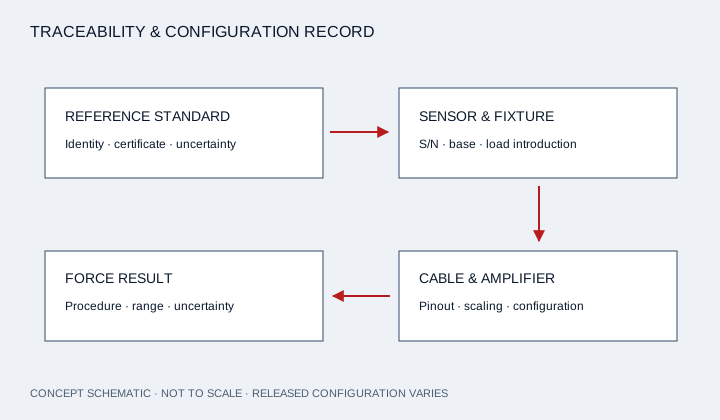
Read a serial-specific certificate before accepting the result.
- Unique sensor serial and full assembly identity
- Force direction, capacity and tested range
- Base, button, cable, amplifier and configuration
- Calibration date, laboratory temperature and humidity
- Reference standard identity, certificate and traceability chain
- Applied force, measured output, zero return and hysteresis
- Procedure, uncertainty, coverage factor and limitations
- Shunt resistor identity, connection points and measured equivalent output
Retrieve an archived record by serial.
Send the exact engraved S/N, model, approximate calibration date and the certificate or shunt information needed. We check identity and available records before replying.
Confidential records are supplied after the relevant unit and entitlement are checked. There is no public certificate database or automatic conformity verdict.
Request calibration record ↗Verify the electrical circuit before reusing a connector.
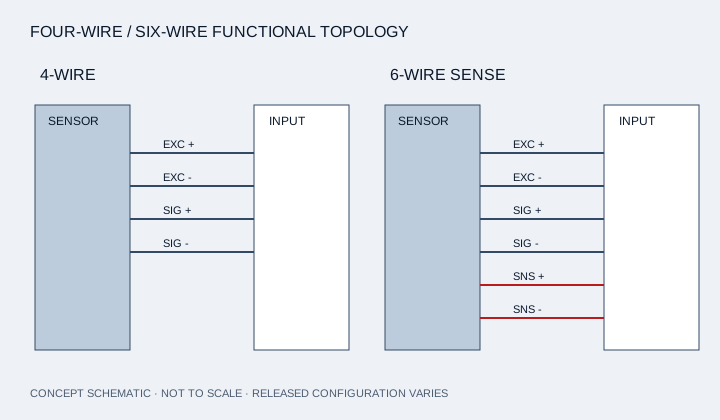
Functional topology only. No pin numbers, colors or excitation limits are declared universal.
Four-wire versus six-wire review.
A four-wire bridge uses excitation and differential signal pairs. A six-wire arrangement additionally brings sense leads to a compatible amplifier to monitor excitation at the sensor. Verify how the amplifier handles sensing before connecting the cable.
Shunt checks verify part of the chain.
A shunt resistor creates an electrical bridge imbalance. Its value, connection points and equivalent output belong to the individual calibration record. It does not apply a traceable mechanical force or verify mounting, hysteresis or the complete load path.
Read the original Interface shunt guidance ↗| Circuit function | Confirm on the released record |
|---|---|
| Excitation + / − | Approved excitation range and regulated supply; never infer it from the connector shell. |
| Signal + / − | mV/V range, tension/compression polarity, amplifier input and overload behavior. |
| Sense + / − | Remote-sense support, terminal mapping and any required amplifier-specific links. |
| Shield / chassis | Approved shield termination, EMC routing, strain relief and isolation from power conductors. |
| Shunt / TEDS | Specified shunt terminals and resistor; TEDS option, reader and stored sensor identity. |
| Two bridges | Separate excitations and outputs, electrical connections, two calibration records and comparison limits. |
A six-pin housing can carry different assignments. Confirm the brand, model, bridge version and cable revision rather than wiring by color alone. Ask for the exact mating connector and pinout with your STEP / datasheet request.
Take a complete calibration brief into the quotation.
Family selection workbook ↓
Compare requested force ranges, load directions and interface review inputs.
PDF · ENGINEERING WORKBOOKMounting & wiring review guide ↓
Plan the flange joint, thread engagement, four/six-wire chain and shunt check.
PDF · ENGINEERING WORKBOOKCalibration evidence workbook ↓
Request the measurement procedure, uncertainty chain and serial-specific documents.
CSV · ENGINEERING WORKBOOKMechanical interface review sheet ↓
Record original and proposed dimensions separately, with drawing revisions.
CSV · ENGINEERING WORKBOOKBlank five-point measurement plan ↓
Plan zero / 25 / 50 / 75 / 100% points; all measured fields are blank.
Bring the load path.
We’ll review the fit.
Send your capacity, center thread and mounting envelope. Include the full original part number when replacing an installed sensor.
CAD and test reports are supplied for the agreed configuration. No generic drawing is presented as an approved production part.
Published and reviewed 2026-10-27 · Responsible publisher: Magatom Dynamics Co., Ltd.