
Mating Bases, Spherical Load Buttons & Digital Kits
Specify the sensor, mounting hardware and acquisition chain together. MT-PLC-ACC options support a controlled installation boundary and a documented calibration configuration.
Four options that belong in the same quotation.
| Option | Indicative increment | Confirm before ordering |
|---|---|---|
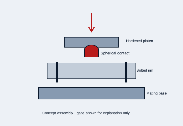
| Precision ground mating mounting base | +$85–$180 | Flatness, stiffness, fastener grade, bolt circle and calibration boundary |
| Thread-in hardened spherical load button | +$45 | Thread, contact radius, hardness, engagement and installed height |
| Dual redundant Wheatstone bridge | +$120 | Independent excitation, two outputs, connector and channel comparison |
| Pre-calibrated USB / 0–10 V / 4–20 mA / EtherCAT amplifier kit | +$150 | Requested interface, sample rate, filter, scaling and combined calibration scope |
Budgeting increments are owner-supplied planning figures. Final configuration, protocol availability, calibration, base sensor, tax and shipping are quoted separately.
From millivolts to a useful force channel.
Agree bridge excitation and input range first. Then specify force bandwidth, acquisition sample rate, filtering, PLC update time and units. A fast network interface alone does not establish force-measurement bandwidth.
For pre-calibrated kits, request the exact sensor serial, amplifier configuration, force points, polarity, uncertainty and mounting hardware used during calibration.
Two bridges support two independent measurements. Redundancy does not by itself establish SIL, PL or a certified safety function.
Match the output to the receiving instrument.
| Signal option | Confirm in the measurement-chain brief |
|---|---|
| Passive mV/V | Excitation, bridge resistance, sensitivity, polarity and amplifier input. |
| USB acquisition | Host/software, sample rate, filter, synchronization and units. |
| 0–10 V / 4–20 mA | Supply, input impedance, scaling, zero/range and fault behavior. |
| EtherCAT | Exact amplifier, process data, cycle timing, synchronization and engineering support. |
| Dual bridge | Independent excitations, outputs, acquisition channels and comparison limits. |
| TEDS | Sensor option, compatible reader, data fields and calibration update policy. |
| Cable / connector | Exact pin assignment, shielding, sense conductors, length and strain relief. |
Signal protocol, force bandwidth and calibration scope are reviewed independently. The quoted kit identifies the actual sensor and amplifier configuration.
Approve the calibration boundary with the fixture.
Specify whether the calibration covers the sensor alone or the sensor, mounting base, button, cable and amplifier as a system. Request traceability and uncertainty for the actual force range and direction.
Review calibration, standards and record requirements ↗For a replacement, retain the full original model, both drawing revisions and the receiving instrument configuration. Machine verification is a separate acceptance step.
Request a calibration plan ↗Bring the load path.
We’ll review the fit.
Send your capacity, center thread and mounting envelope. Include the full original part number when replacing an installed sensor.
CAD and test reports are supplied for the agreed configuration. No generic drawing is presented as an approved production part.