
Pancake Load Cell Working Principle & Mounting Guide
A pancake load cell uses radial shear webs between a central loading hub and an outer bolted rim. Understand the force path, then control the support, contact alignment and measurement chain.
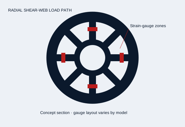
How radial shear webs produce an axial-force signal.
Applied axial force strains the elastic webs joining the central hub to the flange. Bonded strain gauges change resistance with strain; the Wheatstone bridge converts those changes into a differential mV/V output under excitation.
A symmetric gauge arrangement can reduce sensitivity to parasitic moments. The actual cancellation, stiffness and cross-sensitivity depend on geometry, gauge placement and adjustment. Eight-gauge layouts are a design option, not proof of a universal side-load limit.
In searches for “ring and pancake load cells,” the mounting architecture matters: this site covers flange-supported radial-web cells with central load introduction.
Use eccentricity to define the moment review.
For an axial force F applied at an eccentricity e, the associated bending moment is M = F × e. Keep units consistent: N × m gives N·m.
Submit axial force, side force, moment and torque together. Their simultaneous allowable envelope must come from the selected configuration. A survival limit and measurement error are different specifications.
Installation sequence for the actual flange.
- Check the released base stiffness, surface condition and fastener access.
- Align the load path and retain clearance from the compliant sensing structure.
- Use the drawing-specific bolt grade, tightening order and torque.
- Route the cable with strain relief and protect it from moving fixtures.
- Zero, apply known force points and review repeatability after final installation.
Separate non-linearity from system uncertainty.
Non-linearity describes one deviation from a specified reference relationship. Hysteresis, creep, repeatability, temperature, amplifier behavior and fixture alignment can also affect the result. A ±0.03% FS non-linearity target is not automatically a ±0.03% measurement uncertainty.
Fatigue testing also requires mean force, alternating amplitude, waveform, frequency and cycle count. A 10^8-cycle claim needs a defined spectrum and validation record.
Specify fatigue and dual-bridge requirements ↗Original manufacturer references
Interface 1201: original manufacturer product record ↗HBK U10M: original manufacturer configuration and documents ↗Interface: low-profile product family directory ↗Reviewed 2026-10-27. Reference data describes the original manufacturers’ products. It does not certify MT-PLC equivalence.
Specify the joint before assigning a tightening torque.
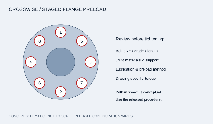
Concept sequence. Actual hole count, staged preload, lubrication and torque are drawing-specific.
- Identify screw size/pitch, grade, length, washer/counterbore and joint materials.
- Approve base flatness, support stiffness, contact condition and the intended calibration boundary.
- Use the specified crosswise/staged tightening procedure and lubrication condition.
- Record minimum effective thread engagement, maximum insertion depth, lock-nut arrangement and clearance to internal parts.
- Keep sensing clearances and any original anti-screw-through device intact; do not assume the proposed sensor has the same stop geometry.
- After assembly, check zero, known force points and repeatability in the installed configuration.
| Parameter | Required release information | Acceptance record |
|---|---|---|
| Bolt torque | N·m or lbf·ft, bolt grade, lubricant and tightening sequence | Drawing revision + approved torque record |
| Center loading thread | Size, pitch, tolerance, engagement, insertion stop and lock nut | Thread inspection + assembly check |
| Mating base | Stiffness, hardness, flatness, parallelism and locating pilots | Surface/dimensional inspection |
| Clearance | Sensing gap, fastener access, deflection and cable movement | Installed clearance check |
HRC and flatness values in an original manufacturer manual apply to that stated configuration. Do not transplant an original torque, 0.005 mm flatness target or insertion depth into a different MT-PLC joint without review.
Verify the electrical circuit before reusing a connector.
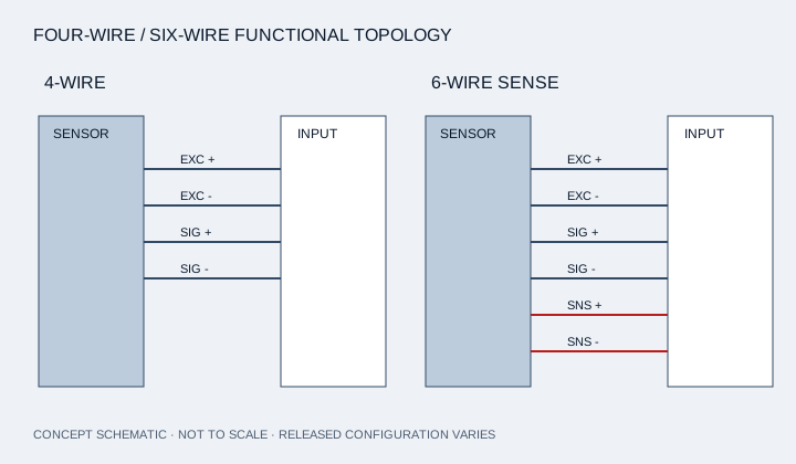
Functional topology only. No pin numbers, colors or excitation limits are declared universal.
Four-wire versus six-wire review.
A four-wire bridge uses excitation and differential signal pairs. A six-wire arrangement additionally brings sense leads to a compatible amplifier to monitor excitation at the sensor. Verify how the amplifier handles sensing before connecting the cable.
Shunt checks verify part of the chain.
A shunt resistor creates an electrical bridge imbalance. Its value, connection points and equivalent output belong to the individual calibration record. It does not apply a traceable mechanical force or verify mounting, hysteresis or the complete load path.
Read the original Interface shunt guidance ↗| Circuit function | Confirm on the released record |
|---|---|
| Excitation + / − | Approved excitation range and regulated supply; never infer it from the connector shell. |
| Signal + / − | mV/V range, tension/compression polarity, amplifier input and overload behavior. |
| Sense + / − | Remote-sense support, terminal mapping and any required amplifier-specific links. |
| Shield / chassis | Approved shield termination, EMC routing, strain relief and isolation from power conductors. |
| Shunt / TEDS | Specified shunt terminals and resistor; TEDS option, reader and stored sensor identity. |
| Two bridges | Separate excitations and outputs, electrical connections, two calibration records and comparison limits. |
A six-pin housing can carry different assignments. Confirm the brand, model, bridge version and cable revision rather than wiring by color alone. Ask for the exact mating connector and pinout with your STEP / datasheet request.
Prepare the installation and calibration record together.
Family selection workbook ↓
Compare requested force ranges, load directions and interface review inputs.
PDF · ENGINEERING WORKBOOKMounting & wiring review guide ↓
Plan the flange joint, thread engagement, four/six-wire chain and shunt check.
PDF · ENGINEERING WORKBOOKCalibration evidence workbook ↓
Request the measurement procedure, uncertainty chain and serial-specific documents.
CSV · ENGINEERING WORKBOOKMechanical interface review sheet ↓
Record original and proposed dimensions separately, with drawing revisions.
CSV · ENGINEERING WORKBOOKBlank five-point measurement plan ↓
Plan zero / 25 / 50 / 75 / 100% points; all measured fields are blank.
Bring the load path.
We’ll review the fit.
Send your capacity, center thread and mounting envelope. Include the full original part number when replacing an installed sensor.
CAD and test reports are supplied for the agreed configuration. No generic drawing is presented as an approved production part.